Feature Gems & Gemology, Winter 2022, Vol. 58, No. 4

A Canary in the Ruby Mine: Low-Temperature Heat Treatment Experiments on Burmese Ruby
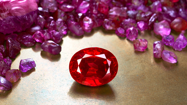

Figure 1. A faceted heated ruby from Mogok, Myanmar, weighing more than 3 ct, stands out against a backdrop of untreated ruby rough from the same origin. The striking appearance of Mogok ruby is highly sought after. Photo by Wimon Manorotkul; faceted ruby courtesy of Kiarttichatra Intarungsee.

ABSTRACT

Detection of heat treatment below 1200°C in ruby and sapphire can present challenges to gemologists, as alterations to the material are often subtle. In this study, the authors heated Burmese ruby samples from Mogok, Myanmar, at temperatures ranging from 600° to 1500°C. The samples were documented using macrophotography, photomicrography of inclusions, ultraviolet fluorescence imaging, and spectroscopic analysis (Raman, ultraviolet/visible/near-infrared, and infrared) to record any changes, with a focus on features that could help detect heat treatment.

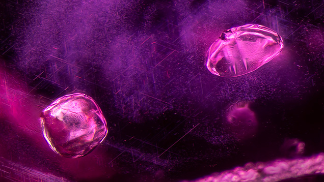
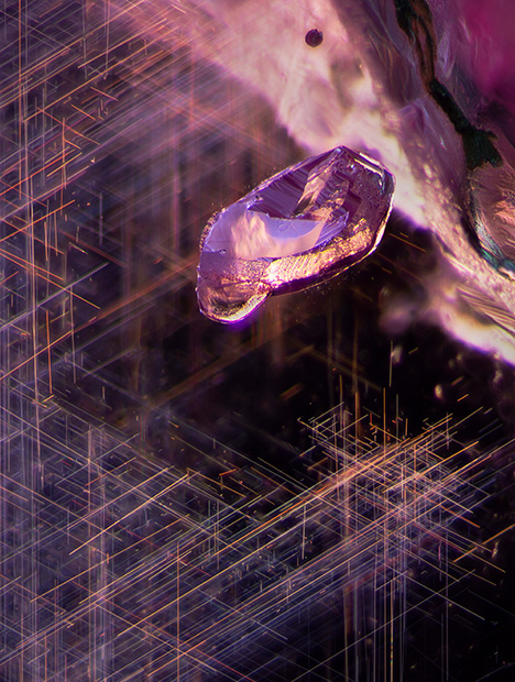
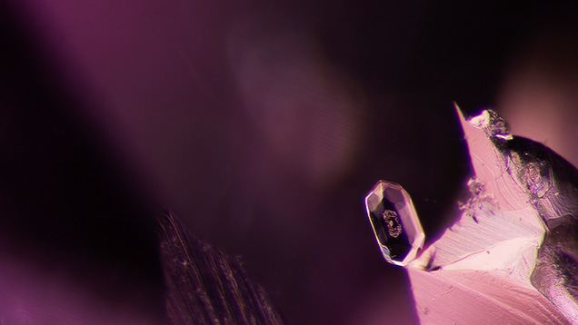
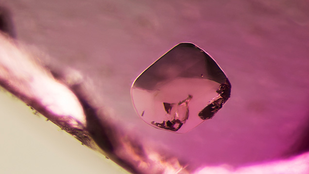
A wide variety of solid inclusions, including calcite, mica, spinel, and zircon, were found in Mogok ruby. Many of those were found to be sensitive to heat treatment with regard to morphology and phase transition; their reactions varied depending on a number of factors such as size, distance from the surface, and species. Microscopic examination provided useful visual indications of heat treatment, even at lower temperatures. Raman analysis of calcite and spinel inclusions also proved valuable in providing complementary evidence of low-temperature heat treatment.

Due to the value and rarity of fine gems, early pioneers developed techniques to treat lower-quality material, including fracture filling and heat treatment. With ruby and sapphire, records of heat treatment go back more than a thousand years (Al-Beruni, 1989).

Heat-treatment temperatures were pushed higher as furnace technology improved with the advent of electricity, reaching temperatures of 1500°–1800°C (corundum melts at 2040°C). Thankfully, this type of treatment tends to be easy to spot because the high temperatures produce significant alterations (Hughes et al., 2017). Although technological advances have allowed for a wider range of treatments, many consumers still appreciate the natural beauty of gems, and there is a premium on untreated ruby and sapphire of high quality.

Because of this market premium, some treaters have returned to heating ruby at lower temperatures, hoping to evade detection. In other cases, extremely high heat is not required to create the desired change. Whatever the reason, identification of low-temperature-treated ruby is often challenging for laboratory gemologists. Thus, this study aims to find useful indicators that corundum has been heat treated at lower temperatures.

BACKGROUND

This project focuses specifically on marble-related ruby, for which Mogok (figure 1) is the most important source in terms of value. Most research on low-temperature treatment has been focused on East African amphibole-related ruby and so-called metamorphic sapphire from extensive secondary deposits in Madagascar and Sri Lanka (Pardieu et al., 2015; Sripoonjan et al., 2016; Hughes and Perkins, 2019).

We define high-temperature treatment as that which involves the dissolution of secondary-phase microcrystals. In corundum, the most common of these microcrystals is rutile silk, which tends to dissolve with heat at temperatures of approximately 1200°–1350°C. Thus, treatment in this temperature range is considered the boundary between “low” and “high” heat in corundum (Hughes et al., 2017).

Rutile silk in ruby and sapphire comes from a variety of sources. As a result, its altered appearance has become a key indicator of heat treatment. But because rutile tends to be affected by heat only at 1200°C or above, it is not a reliable indicator of lower-temperature heat treatment. Thus, we wanted to determine whether other types of solid inclusions are more sensitive to heat at lower temperatures.

Mica and amphibole crystals, for example, are commonly seen in Mozambique ruby but do not always react to heat in the same way. Mica crystals have been reported to be the more sensitive of the two, frequently displaying visual alteration after treatment at low temperatures, while amphibole crystals are less likely to display damage when heated to the same temperatures (Pardieu et al., 2015).

In a previous era, coal miners learned to be cautious of the air quality while mining. Dangerous gases such as carbon monoxide could build up in a mine, causing illness or even death. To prevent this, miners began bringing canaries down into the mine. These birds are highly sensitive to poisonous gases, so if one died it was a signal to evacuate. From this came the expression “canary in a coal mine,” referring to an early warning of potential trouble.

Our experiments aimed to detect something similar: an “early” warning at lower temperatures that could signal heat treatment in corundum. What crystal inclusions might act as the metaphorical canary in our ruby mine?

MATERIALS AND METHODS

Samples. A total of 46 samples from Mogok were selected for study. For this project, the authors did not analyze rubies from the Mong Hsu area, which is the second major ruby mining area in Myanmar (Peretti et al., 1995). While Mong Hsu also produces ruby of commercial importance, its appearance and internal features make it distinct from the Mogok material. Mong Hsu stones tend to have fewer crystal inclusions, making the Mogok material better suited for these experiments. Research on low-temperature heat treatment of Mong Hsu ruby would be a fascinating avenue for further study but was beyond the scope of this project.

Samples 1–44 were selected from a larger parcel of rubies reportedly from Myanmar that was purchased from a Burmese trader in Bangkok. Examination of the parcel showed that all had characteristics (inclusion scene, fluorescence, and trace element composition) consistent with those of untreated ruby from Mogok. The samples were chosen for their interesting solid inclusions as well as their color range from pink to red.

In addition, samples 45 and 46 were selected from GIA’s reference collection. Both rubies were collected directly by GIA gemologists from mine rejects in the village of Baw-Lon-Gyi in Mogok. Sample 46 was chosen because it had areas free of inclusions that made it suitable for high-quality ultraviolet/visible/near-infrared (UV-Vis-NIR) spectros­copy. Samples 1–45 were polished into unoriented wafers measuring approximately 1.4–3.2 mm in thickness, with diameters ranging from 2.2 to 5.7 mm. Due to the nature of the rough ruby crystals, most of these wafers were oriented approximately perpendicular to the c-axis, resulting in a color dominated by the more purplish o-ray component. Sample 46 was polished into a wafer with surfaces oriented perpendicular to the c-axis with a tolerance of less than 2°, ideal for spectroscopy.

Of the 46 samples, 15 were chosen for heating experiments (samples 4, 8, 10, 11, 12, 17, 18, 22, 25, 30, 37, 39, 40, 45, and 46). These were selected to represent the diversity of mineral inclusions observed in ruby from Mogok. The 31 samples that were not heated were analyzed to identify and document their inclusions.

Photography and Photomicrography. Photos were taken with a Canon EOS 6D camera with a 65 mm lens mounted to a copy stand. The samples were placed on a light box illuminated by an XD-300 xenon white light source.

Samples were observed before and after each round of heat treatment using an Olympus SZX16 microscope with an SDF PLAPO 0.8× objective lens. Photomicrographs were taken with the same microscope, connected to a Canon EOS 6D camera using a Spot Imaging DE25TMT microscope adapter. Illumination was provided by a modified Motic darkfield base, supplemented by fiber-optic illuminators.

Raman Spectroscopy. To identify mineral inclusions, Raman spectra were obtained using a Renishaw inVia Raman system fitted with a 514 nm argon-ion laser attached to a Leica DM2700M microscope. Spectra were collected in the range of 200–1200 cm–1. The grating was 1800 l/mm with a spectral resolution of 1 cm–1. Exposure time was 10 s at 100% light power using a 6 mW laser. Accumulations were set at a minimum of three until the spectra’s signal-to-noise ratio was greater than 10 and the major identifying peaks could be visually resolved from the background noise. Calibration was performed using the 520.5 cm–1 line of a silicon wafer. In all cases, entries from the RRUFF database (Lafuente et al., 2015) were used as references when identifying inclusions. Spectral comparisons were performed with Renishaw Wire (version 3.4) software. This analysis was conducted on most solid crystals and repeated on selected crystals after each heating step. All spectra were collected at room temperature.

UV-Vis-NIR Spectroscopy. For samples 4, 8, 10, 11, 12, 17, 18, 22, 25, 30, 37, 39, and 40, UV-Vis-NIR spectroscopy was conducted with a Magilabs GemmoSphere UV-Vis-NIR spectrometer before and after each stage of heating. The wavelength range was 365–1000 nm, with a resolution of 1.3 nm and an integration time of 40 ms.

With samples 45 and 46, UV-Vis-NIR spectra were collected with a Hitachi U-2910 spectrophotometer using a wavelength resolution of 1.5 nm. The spectra obtained were corrected by calculating the reflection loss from the refractive index data, and the data was converted to show their absorption coefficients (α, cm–1) using α = 2.303A/d, where A is absorbance and d is the path length in centimeters. The ruby samples were mounted in wax-coated aluminum plates with a 1 mm hole to ensure consistent measurements throughout the experiment.

Infrared Spectroscopy. Fourier-transform infrared (FTIR) spectroscopy was performed using a Bruker Tensor 27 spectrometer before and after each stage of heating on the 15 heated samples. Each specimen was placed on a Pike DRIFTS attachment and scanned 16 times at a resolution of 4 cm–1.

Trace Element Analysis. Trace element chemical analyses were performed on all samples using laser ablation–inductively coupled plasma–mass spectrometry (LA-ICP-MS) technology with a Thermo Fisher Scientific iCAP Q ICP-MS coupled with a Q-switched Nd:YAG laser ablation device (Electro Scientific Industries Inc. New Wave NWR213) operating at a wavelength of 213 nm. The laser ablated spots were 55 μm in diameter, created using a laser fluence of approximately 10 J/cm2 with a repetition rate of 10 Hz and a dwell time of 40 s. The forward power was set at 1350 W, and the typical nebulizer gas flow was at approximately 0.80 L/min. A special set of corundum reference standards was used for quantitative analysis of beryllium, magnesium, titanium, vanadium, chromium, iron, and gallium (Stone-Sundberg et al., 2017, 2021), whereas NIST Standard Reference Materials 610 and 612 glasses were used for other elements. All elemental measurements were normalized on aluminum as the internal elemental standard.

Ultraviolet (UV) Fluorescence Imaging. The 15 heated samples were observed in both long-wave and short-wave UV radiation using two different methods. One method was with a standard UV light box. We used an Ultraviolet Products UVLS-26 EL Series UV lamp using a 6-watt bulb, with a long-wave light source at 365 nm and a short-wave light source at 254 nm. We also placed each specimen in a Magilabs custom-designed deep-UV fluorescence system, consisting of a fluorescence microscope equipped with a high-intensity pulsed xenon flash lamp with an interference bandpass filter at 228 nm.

Fluorescence photography was taken with the samples placed in the Magilabs system attached to a Wild M400 Photomakroskop with an attached Canon EOS 6D camera. For long-wave images, we used an external Convoy S2+ 4-watt UV flashlight. For short-wave images, we used the built-in illumination from the Magilabs system at 228 nm.

HEATING EXPERIMENT

Sample Selection. As previously mentioned, 15 of the 46 samples examined were selected for heat treatment experiments. Thirteen of the samples (numbers 4, 8, 10, 11, 12, 17, 18, 22, 25, 30, 37, 39, and 40) were chosen for their diverse inclusion scenes featuring a wide variety of solid inclusions. Two additional samples (numbers 45 and 46) were selected with a focus on spectroscopy. These had areas that were free of inclusions. Sample 45 was on the lighter end of the color range and 46 on the darker end, giving us examples of how different shades might react to heat treatment.

Heat Treatment. For the first four rounds of heat treatment, the 15 samples chosen were placed on a piece of synthetic corundum felt and heated in a Vulcan 3-550 oven in air, which is an oxidizing atmosphere. They were heated to 600°, 750°, 900°, and 1100°C and kept at their maximum temperature for four hours. After each heating round, the samples were cooled down to room temperature and data was collected on each sample.

The specimens were also heated for a final round by John Emmett (Crystal Chemistry, Brush Prairie, Washington) and Eric Braunwart (Columbia Gem House, Vancouver, Washington). Treatment conditions were 1500°C in a flowing oxygen atmosphere for five hours in a Thermal Technology Inc. 3060 furnace. This round took the stones into the realm of high-temperature heat treatment.

RESULTS AND DISCUSSION
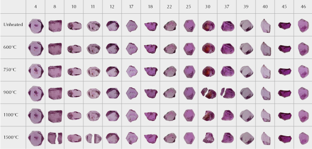
Figure 2. The 15 ruby samples from the experiments, before heat treatment and after each stage of heating. While the overall bodycolors did not show significant changes, there were changes to clarity as the inclusions altered. Sample 30 in particular showed a dramatic change in color due to the alteration of iron staining in a large fissure. Four samples (8, 11, 30, and 37) broke apart during heat treatment. We continued to heat the larger of the two pieces in subsequent rounds. Photos by Sora-at Manorotkul.

Appearance. All 15 heated ruby samples were examined and photographed before and after heat treatment under controlled lighting conditions. Across the various rounds of heating, the 15 selected samples did not display significant alteration in bodycolor, but we did notice many inclusion changes. One of the most notable was to sample 30, which contained a large fissure with orange iron staining. After the first round of heating, the stain deepened in color; this change was eye visible (see figure 2).

Another dramatic change was that some rubies broke apart during heat treatment. Samples 30 and 37 split after heating to 900°C, while samples 8 and 11 split after heating to 1500°C. Following this 1500°C heating round, another small corner of sample 30 broke off, but we were unable to recover the fragment. For the rubies that broke apart, we continued to heat the larger of the two pieces.
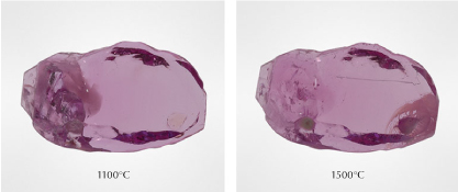
Figure 3. When heated to 1500°C, a cluster of inclusions on the left side of sample 10 became less obvious. On the right side, the alteration of a sphene crystal created clarity issues. Photos by Sora-at Manorotkul.

In many cases, the treatment affected clarity. Figure 3 compares sample 10 after heating to 1100°C and 1500°C. The left side of the specimen shows a darker fissure beginning to heal as well as a cloud of rutile silk that is less visible, improving the clarity of that side of the stone. But on the right side, a sphene crystal melted and lowered the clarity in that section.

INTERNAL FEATURES

Figure 4. A: In sample 5, transmitted light reveals a variety of transparent rounded crystals of relatively high relief compared to the surrounding corundum. They appear to be nearly colorless. B: The same crystals in darkfield illumination. C: Between crossed polarizers, the same crystals display interference colors, suggesting that they are doubly refractive. Micro-Raman analysis identified these as calcite. Photomicrographs by E. Billie Hughes; field of view 2 mm.
Figure 5. In sample 6, a pair of calcite crystals stands out above a cloud of undissolved rutile silk needles. Note the twinning planes in both crystals, a common feature for calcite. Photomicrograph by E. Billie Hughes; field of view 2 mm.
Figure 6. A mica crystal in sample 28, surrounded by a cloud of undissolved rutile silk. While this type of silk is a hallmark of untreated Burmese ruby, it can also be seen in stones heated at relatively low temperatures. Photomicrograph by E. Billie Hughes; field of view 3 mm.
Figure 7. A zircon crystal in an untreated Burmese ruby, sample 41. Zircon was a frequent inclusion in the Burmese ruby samples. Photomicrograph by E. Billie Hughes; field of view 2 mm.
Figure 8. Spinel crystals, such as this one in sample 15, were seen frequently in the Burmese ruby samples. Photomicrograph by E. Billie Hughes; field of view 3 mm.

Solid Inclusions. A variety of mineral inclusions were identified in the 46 samples using Raman spectroscopy. The most common solid mineral inclusion observed was calcite (figures 4–5). Mica (figure 6), zircon (figure 7), and spinel (figure 8) were also frequently observed. Rutile and sphene (titanite) were occasionally seen. Apatite, CO2-rich fluid inclusions, diaspore, feldspar, garnet, iron sulfide, and scapolite were detected infrequently in our ruby samples.
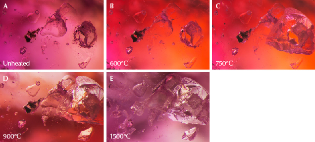
Figure 9. A: In sample 30, the large transparent crystal in the center is spinel, and on the right is a calcite crystal containing liquid CO<sub>2</sub>. B: The background color has changed dramatically because the color of the stained fissure in the background has altered significantly. The ruby’s bodycolor does not appear to have undergone major change. C: The crystal to the right has exploded, leaving a small surface-reaching hole. On the top left, a glassy discoid can be seen around a small crystal. D: The staining in the background has again changed color. E: Much alteration is visible, with partially healed fissures in several spots. Photomicrographs by E. Billie Hughes; field of view 2 mm.
Figure 9. A: In sample 30, the large transparent crystal in the center is spinel, and on the right is a calcite crystal containing liquid CO2. B: The background color has changed dramatically because the color of the stained fissure in the background has altered significantly. The ruby’s bodycolor does not appear to have undergone major change. C: The crystal to the right has exploded, leaving a small surface-reaching hole. On the top left, a glassy discoid can be seen around a small crystal. D: The staining in the background has again changed color. E: Much alteration is visible, with partially healed fissures in several spots. Photomicrographs by E. Billie Hughes; field of view 2 mm.

Inclusion Documentation. Each specimen was examined and photographed in the microscope before and after every stage of treatment. The changes to solid inclusions tended to follow a pattern as the samples were heated to increasing temperatures. Notable changes included the following:

  1. Alterations to fissure stains: Epigenetic iron staining in fissures in corundum is known to be impacted by heating to temperatures as low as 350°C (Koivula, 2013). In our experiments, the staining stood out in one ruby in particular: sample 30. Even after our first round at 600°C, this staining displayed a dramatic change in appearance, becoming a brighter, deeper reddish orange. This is visible in the background of figure 9.
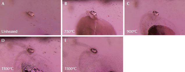
Figure 10. A: A transparent rounded zircon crystal in sample 4. B: A large, shiny fissure has developed. C: The fissure has begun to heal at the edges, creating a “fingerprint” pattern at the top and leaving a glassy area at the bottom. D: The fissure has further healed, producing many fine channels, while the glassy area has largely disappeared; the texture of the surface of the zircon crystal itself has also altered and become less smooth. E: The fingerprint has expanded, and many of the elongated channels have “necked down” to form smaller bubble-like features. Photomicrographs by E. Billie Hughes; field of view 1.5 mm.
Figure 11. A: An elongated mica crystal surrounded by several smaller crystals in sample 8. B: There is little noticeable change except at the top left, where a small fissure has formed. C: The scene shows obvious signs of heat alteration. In addition to the fissures seen earlier, glassy discoids appear around crystals in the background, and a shiny fissure is conspicuous around the biotite crystal in the foreground. D: Some fissures have begun to heal; the glassy fissure around the biotite crystal has developed elongated channels, and the partially healed edges of the glassy discoid at the top of the frame have started to neck down and become wider. E: The scene has changed dramatically; glassy discoids and partially healed fissures with a melted appearance are visible across the field of view, and the biotite crystal has developed an immobile gas bubble in its center. Images A and B were captured with darkfield illumination; diffused fiber-optic illumination has been added in C–E to reveal the fissures more clearly. Photomicrographs by E. Billie Hughes; field of view 1.5 mm.
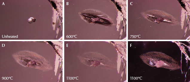
Figure 12. A: A calcite crystal from sample 40, shown in its untreated state. B: A glassy fissure has developed around the crystal. C: The edges of the fissure have begun to heal and assume a cloudy appearance. D: Further healing in the fissure. E: Almost all of the glassy areas have disappeared as the fissure has healed. Meanwhile, the calcite crystal has become more opaque. F: Darkfield illumination shows detailed channels in the fingerprint around the calcite, which is becoming whiter and more opaque. Photomicrographs by E. Billie Hughes; field of view 2.2 mm.
  1. Formation and subsequent healing of fissures: One of the first changes noted was that shiny, smooth fissures began to develop around some solid minerals, often at temperatures as low as 600°–750°C. When heated to temperatures of 900°C and higher, these fissures tended to heal, often starting at the outside edges (figures 10–12). This healing often took the form of elongated channels. As the samples were heated further, these channels “necked down” and separated into shorter, more bubble-like shapes (Roedder, 1984). These partially healed fissures form what gemologists often refer to as “fingerprints.”
Figure 13. A: These mica crystals in sample 40 show a series of striations. B: Fissures have developed around the mica crystals, and the striations have become much less prominent. C: Significant changes are observed, with the entire area on and around the crystals assuming a frosty white appearance. Photomicrographs by E. Billie Hughes; field of view 3 mm.
  1. Alterations in the appearance of solid mineral inclusions: The solid inclusions themselves also tended to follow a pattern in response to increasing temperatures. In addition to developing fissures, many crystals began to display changes in opacity and texture as they were heated to progressively higher temperatures. Their tendency was to become less transparent, often developing a white interior. In many cases they also developed a more textured exterior, sometimes becoming so “frosted” that they appeared opaque. The mica crystals in sample 40 showed some of the most dramatic changes in texture (see figure 13). Heating to 900°C caused linear features to become much less visible. After heating to 1500°C, the crystal was barely recognizable, with a frosty appearance resembling a fresh dusting of snow.
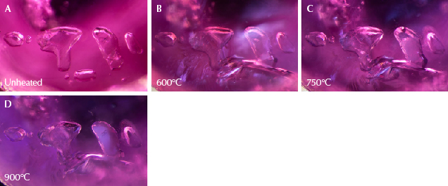
Figure 14. A: A group of transparent calcite crystals in sample 8. B: A large glassy fissure has formed around the cluster. C: The crystal second from the right has changed in texture and become slightly opaque; the one on the far right has also developed a fissure that has begun to heal. D: Note the significant changes to the crystal second from the right, which has taken on a whitish appearance and become opaque. Photomicrographs by E. Billie Hughes; field of view 2 mm.
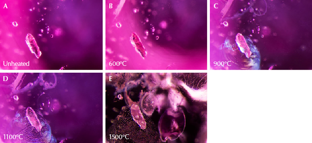
Figure 15. A: In sample 25, the three hexagonal crystals on the left are mica, while the crystal at top right is garnet. The scene also contains nests of undissolved rutile silk in intersecting needles. B: Shiny fissures appear around three of the four crystals. The crystal third from the left does not display a fissure, despite being mica like the first two crystals. The garnet does display a fissure, however. C: All four crystals have altered, and the fissures have begun to heal at the edges. D: More changes can be noted as existing fissures have expanded and healed further. New fingerprints have developed to the right of the garnet crystal. Through four rounds of heat, the rutile silk in the background remains unaltered. E: Fissures now show significant alteration, with cloudy areas and drippy channels. The three mica crystals on the left have become more transparent and contain several immobile gas bubbles. In the background, the rutile silk needles have altered significantly, partially dissolving into shorter, broken needles and dotted particles. The previously “silky” area appears more transparent. Photomicrographs by E. Billie Hughes; field of view 3 mm.

One of the calcite crystals shown in figure 14 went from transparent to displaying a translucent white filling after it was heated to 750°C. Following the next round at 900°C, the white area expanded to the point where the whole crystal was opaque. These observations were not limited to calcite inclusions but were seen across a variety of solid inclusions. Similar patterns were noted with mica (figure 15), spinel (figures 16 and 17), sphene (figure 18), iron sulfide (figure 19), diaspore (figure 20), primary rutile (figure 21), scapolite (figure 22), feldspar (figure 23), and apatite (figures 24–26).

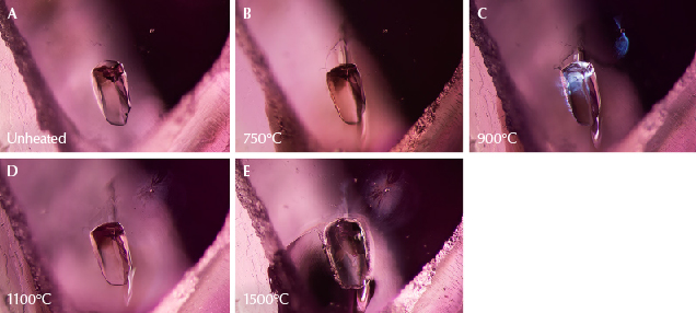
Figure 16. A: This transparent spinel crystal in sample 39 retains the same appearance through subsequent rounds of heating to 600°, 750°, and 900°C. B: The spinel crystal has begun to change in appearance and started to develop elongated lines. C: The crystal has taken on a frosty, whitish appearance. Photomicrographs by E. Billie Hughes; field of view 1.5 mm.
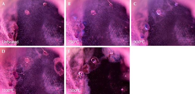
Figure 17. A: Sample 39 shows a spinel crystal in the center, with a small crystal to the top right. B: The large crystal has developed a glassy fissure. C: The smaller crystal also has a shiny fissure. Diffused fiber-optic illumination has been added to the transmitted light used in the other steps to better highlight the fissures. D: The fissures begin to heal, creating fingerprints around the crystals. E: The fissures have expanded and appear cloudier. The larger crystal’s surface has altered, while the smaller crystal displays a more rounded, bubble-like appearance. Photomicrographs by E. Billie Hughes; field of view 3 mm.

Solid Inclusions Most Sensitive to Heat. Some of the solid inclusions stood out as particularly sensitive to heat at lower temperatures. In certain samples, some calcite crystals began to show a reaction even after the first round of heating to 600°C. This can be seen in sample 8 (figure 14) and sample 40 (figure 12). Zircon (figure 10), mica (figures 11, 13, and 15), and spinel (figures 16 and 17) crystals began to display changes after heating to 750°C.
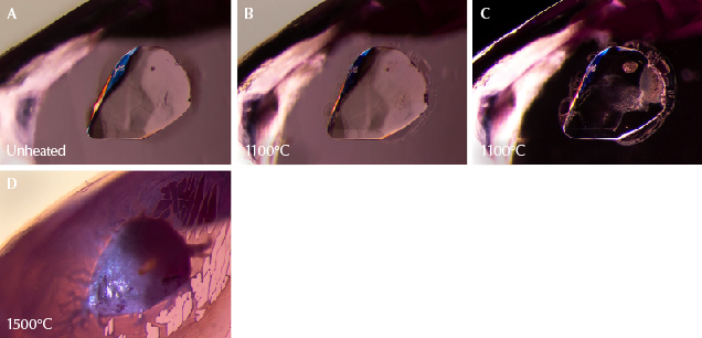
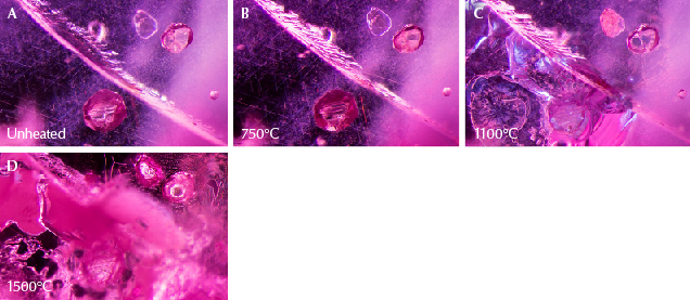
Figure 18. A: A sphene crystal stands out in high relief in sample 10. Heating to 600°, 750°, and 900°C created no noticeable changes. B: The first signs of change, with small fissures forming on the edges of the crystal. Subtle changes to the texture are also visible inside the crystal, which appears less smooth. C: Changes to the crystal’s interior become easier to see in darkfield illumination. D: Dramatic changes, as fissures around the sphene expand and create drippy channels with a melted appearance; the surface is now frosty and opaque. Photomicrographs by E. Billie Hughes; field of view 1.5 mm.
Figure 19. A: Sample 18 contains a variety of interesting inclusions. On either side of this fissure are two angular sulfide crystals set against a background of rutile silk needles. B: The sulfide crystals display subtle fissures at their edges, but the rest of the scene appears unaltered. C: Significant differences appear. Large, shiny fissures have developed, and opacity changes are visible, particularly in the lower sulfide crystal, which now appears whiter and cloudier. In the background, the rutile silk is still intact. D: Many fissures have appeared and begun to heal, partially obstructing the view. However, there are notable changes. The sulfide crystal at the top right has developed an immobile gas bubble. In the background, the rutile silk needles have dissolved. Photomicrographs by E. Billie Hughes; field of view 2 mm.

Fortunately for gemologists, these highly sensitive solid inclusions were also the most common inclusions in the rubies studied, providing a useful visual aid when trying to detect low-temperature heat treatment.

Scapolite, which we found in fewer samples, also began to show changes at the slightly higher temperature of 900°C (see figure 22). This makes it another helpful sign of heat, but one that we expect to see less frequently.
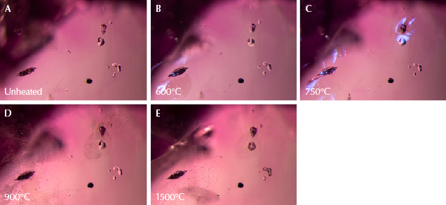
Figure 20. A: A variety of solid inclusions are present in sample 22. At left is a crystal containing diaspore, on the right are several transparent spinel crystals, and at the bottom right is a dark, rounded crystal of primary rutile. B: Changes are already visible, with a glassy fissure around the diaspore crystal on the left. Diffused fiber-optic illumination has been added to the transmitted light used for the other images in this set to accentuate the fissure. C: A fissure has also developed around the top of the spinel crystal. Again, diffused fiber-optic illumination has been added. D: The fissures that developed in previous stages have begun to heal and form fingerprints. E: These fissures heal further and melted-looking channels appear. Photomicrographs by E. Billie Hughes; field of view 2 mm.
Figure 21. A: Sample 37 shows dark crystals of primary rutile, along with clouds of exsolved rutile silk. B: Small fissures have begun to form around some of the primary rutile crystals. C: The fissures have expanded and begun to heal, though the primary rutile crystals appear unaltered and the rutile silk needles in the background are intact. Photomicrographs by E. Billie Hughes; field of view 2 mm.

Solid Inclusions Less Sensitive to Heat. Other solid inclusions had to be heated to higher temperatures before they displayed clear visual changes. Crystals of sphene (figure 18), primary rutile (figures 20 and 21), and feldspar (figure 23) in our specimens did not show changes until they were heated to 1100°C. Some apatite crystals also began to display alteration at this temperature, but one apatite in sample 46 did not display clear changes until the last round of heating to 1500°C (figure 26).

Figure 22. A: This scapolite crystal in sample 12 displays a distinctive shape, similar to a lowercase “r.” B: The scapolite begins showing signs of alteration. Diffused fiber-optic illumination was added to the darkfield illumination used for the previous image to highlight the shiny fissures that developed around the scapolite. C: Major changes are evident, as many fissures have formed and then healed with elongated channels that have a drippy appearance. The scapolite crystal has developed opaque areas and immobile gas bubbles. Photomicrographs by E. Billie Hughes; field of view 2 mm.
Figure 23. A: A cluster of feldspar crystals in sample 37 that show no alteration through several rounds of heating. B: The feldspar crystals are intact and appear unaffected by heat. However, discoid fissures appear in the background at the top left and bottom right. C: Many more fissures have developed, including some around the feldspar crystals in the center. Photomicrographs by E. Billie Hughes; field of view 1.7 mm.

Impact on Rutile Silk. One of the hallmarks of ruby from Mogok is the presence of rutile silk, often in dense nests of unbroken needles (see figure 6). In fact, the point at which rutile silk begins to dissolve is often cited as the boundary between “low-temperature” and “high-temperature” heat. Rutile generally begins to dissolve at around 1200°–1350°C (Hughes et al., 2017).
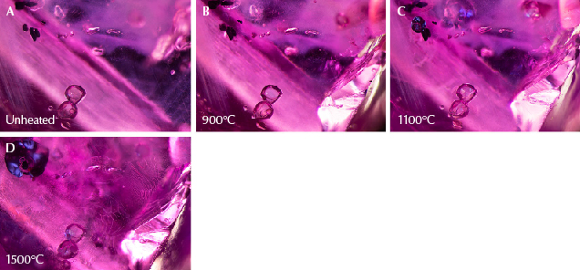
Figure 24. A: At the bottom are rounded apatite crystals in sample 37. Toward the top left are dark primary rutile crystals, and at top center are transparent feldspar crystals. B: A portion of the sample has broken at the bottom right corner, yet the scene appears largely unaltered. C: One of the small rutile crystals at top left has a dark, shiny discoid around it, and glassy fissures appear in the background at the top. Small fissures are developing around the apatite crystals at the bottom. D: The shiny dark discoid in the top left corner has expanded, and large drippy fingerprints are prominent across the scene. Photomicrographs by E. Billie Hughes; field of view 3 mm.
Figure 25. A: Sample 37 shows a rounded apatite crystal next to a fissure, with rutile silk needles at the bottom. B: Part of the sample has broken at the site of the fissure, as seen on the right of the image. Still, the apatite crystal does not show clear signs of alteration. C: A shiny fissure has developed around the crystal, indicating heat damage. D: The crystal has a more frosty texture, and the fissure around it has begun to heal. Photomicrographs by E. Billie Hughes; field of view 1 mm.
Figure 26. Left: Sample 46 contains a rounded apatite crystal (the larger crystal on the left with the dark triangle) and a small transparent zircon crystal immediately to its right. Remarkably, the apatite crystal remains unchanged until the last round of heating. Right: After heating to 1500°C, the apatite crystal has developed a partially healed fracture around it and become more whitish and opaque. The zircon crystal to the right of it has developed a mottled appearance with a few spots in its interior. On the far right, a partially healed fissure has developed. Photomicrographs by E. Billie Hughes; field of view 1.5 mm.

This was supported by the results of the experiment. In all the samples we heated, the rutile silk showed no noticeable change after heating up to 1100°C. Even as other features began to change, the rutile silk needles remained intact. After heating to 1500°C, the rutile silk dissolved from needles into small dotted particles. In some instances, it dissolved to such an extent that it was no longer visible. This dissolution is particularly clear in figure 15, where the silk that was still intact across the stone at 1100°C has largely dissolved after heating to 1500°C, leaving behind just a few short dotted needles and particles.

Immobile Bubbles. Another notable change to solid inclusions was the development of immobile bubbles, which only appeared after heating to 1500°C. These features are particularly clear in the mica crystals in figures 11 and 15 and the scapolite in figure 22.

When these inclusions reach higher temperatures, they start to break down. Hydrous minerals and carbonates will release volatiles such as water and carbon dioxide when they break down into other minerals. This results in the separating of a vapor phase and a remaining solid phase. In the case of calcite, the breakdown product consists of the mineral lime (CaO) and the gas carbon dioxide. Depending on the complexity of the mineral, the solid phase after breakdown can consist of various components, or it might start to melt (congruently or incongruently) at higher temperatures. Upon quenching, these phases do not have time to crystallize as a single entity. The newly formed phases are preserved, with the solids in a glassy state. Since this glassy material occupies less volume than the previous crystal, the result is an inclusion with a combination of solids (crystalline or glassy) and a vapor phase, seen as an immobile bubble (Roedder, 1984).

Raman Spectroscopy and Heat Treatment. Raman spectroscopy detects a shift in phonons of scattered light when it interacts with a material (the “Raman shift”); this shift is characteristic for each mineral. Every peak in the spectrum corresponds to a specific vibration between molecules within the mineral. While each mineral has a characteristic spectrum defined by its crystal structure, many other variables can influence the vibrations and thus the final spectrum.

Variations in the crystal structure can cause subtle shifts in the spectrum. This includes substitution of certain elements, lattice damage due to radioactivity, and compressed structures due to pressure.

The exact position of the peaks is variable and determined by the conditions under which the analysis is done, as well as the exact composition of the mineral (Gillet et al., 1993). We believe that while the mineral is at room temperature, the pressure on the inclusion is significantly higher since it is still completely encased in its ruby host. This means that the pressure in the inclusion is the same as when it was trapped by the growing ruby deep in the earth.

Another challenge faced in this study comes from the nature of the host material. While confocal Raman spectroscopy allows one to focus on a specific point within the gem, the laser light still has to travel through the corundum host. Ruby absorbs much of the 514 nm wavelength and emits light (fluorescence) as a result. This will always overlay the Raman spectrum and may overpower it to such a degree that the weaker Raman inclusion spectrum drowns in the noise of the ruby’s fluorescence. Despite the high background noise introduced by fluorescence, major peaks of corundum can still be observed. This is characterized by a major peak at 415 cm–1 and smaller peaks at 640, 375, 750, and 575 cm–1 (in decreasing order of relative intensity).

We explored the use of Raman spectroscopy to observe structural changes in solid inclusions in Burmese ruby. It is intuitively understood that heat treatment destroys inclusions, but at lower temperatures it can also anneal any crystal damage in the inclusions, especially in inclusions that tend to contain radioactive elements, which has been observed in Madagascar sapphires (Saeseaw et al., 2020). In our experiments, we focused on the Raman spectra of the calcite, spinel, and apatite inclusions.

Calcite. The Raman spectra of carbonate minerals are characterized by a strong peak in the range of 1080–1095 cm–1 and minor peaks around 155, 280, and 715 cm–1 (Krishnamurti, 1957). For calcite crystals, one interesting case study is that of sample 8 (figure 14), which shows four large carbonate crystals lined up. These calcite crystals exhibit two different behaviors in their Raman spectra during successive rounds of heat treatment.

Figure 27. Raman spectra of calcite (the crystal on the far left in sample 8; see figure 14). The main feature of the spectra, the peak at 1080 cm<sup>–1</sup>, remained consistent after each round of heating. Spectra are offset vertically for clarity.
Figure 27. Raman spectra of calcite (the crystal on the far left in sample 8; see figure 14). The main feature of the spectra, the peak at 1080 cm–1, remained consistent after each round of heating. Spectra are offset vertically for clarity.

Three of the crystals displayed minimal changes, where the peak shape remained similar. These are the same crystals that exhibited no significant visual changes during low-temperature treatment. Figure 27 shows the Raman spectra of the crystal on the far left, which remained similar throughout the heating process.

Figure 28. Raman spectra of calcite (the crystal third from the left in sample 8, see figure 14). After heating to 900°C, the spectrum showed significant changes. Note how the peak at 1080 cm<sup>–1</sup> widens and becomes less sharp, which corresponds to the changes observed in the crystal as it becomes white and opaque. This corresponds to calcite being transformed into lime. Spectra are offset vertically for clarity.
Figure 28. Raman spectra of calcite (the crystal third from the left in sample 8, see figure 14). After heating to 900°C, the spectrum showed significant changes. Note how the peak at 1080 cm–1 widens and becomes less sharp, which corresponds to the changes observed in the crystal as it becomes white and opaque. This corresponds to calcite being transformed into lime. Spectra are offset vertically for clarity.

In contrast, one crystal from this series (the third from the left) looked very similar to the others in its unheated state but reacted strongly to heating. During the first two heating steps (600°C and 750°C), its appearance and Raman spectrum barely changed. At 900°C and above, the Raman spectra show a significant widening of the main carbonate peak as well as a slight shift to higher wavenumbers (see figure 28). Visually, the crystal started to turn white and opaque. The peak between 1080 and 1090 cm–1 corresponds to the symmetric stretching of C-O bonds of carbonate (CO3); such a reduction in the sharpness and intensity of this peak means that the carbonate is decomposed. Additional peaks appearing around 360 cm–1 match with lime (CaO). At higher temperatures, calcite breaks down into lime and CO2, which is probably what we observed here. The Raman spectra did not reveal the presence of CO2, most likely due to its low concentration. It might also have escaped via (hairline) fractures that developed during treatment.

We observed the same reaction in the calcite inclusion in sample 30, but here the breakdown did not start until 1100°C. Thermal decomposition of calcite under atmospheric pressure typically takes place in the range of 750°C (Harker and Tuttle, 1955). These observations of unaltered calcite at temperatures above the reported decomposition temperature show that there are other factors playing a role. Probably the most prominent variable is the pressure under which the inclusion is encased in the host mineral.

The observation of how both the appearance and spectra of the same types of mineral inclusions can vary, despite having been heated to the same temperature, is one of the more thought-provoking results of these experiments. In some cases, as seen with calcite, even the same types of mineral inclusions in the same sample can react differently. This highlights the variety of factors that can influence the behavior of crystals during heat treatment, which are discussed later in this article. Because of the numerous factors that can have an impact, it is difficult to pinpoint just one reason for the inclusions’ differing responses to heat.

Spinel. Another common inclusion in Burmese ruby is spinel. In the last two decades, several heat treatment studies have been performed on gem spinel, often focused on nondestructive analytical detection techniques (Saeseaw et al., 2009; Widmer et al., 2014). Most of the work has concentrated on the photoluminescence of spinel, where changes in the emission spectrum are reliable indicators of heat treatment. Unfortunately, this technique cannot be used for spinel inclusions in ruby, since the photoluminescence spectrum would be dominated by that of the chromium-rich host corundum, so instead we focused on the Raman spectrum.

Figure 29. Raman spectra of the spinel crystal in sample 30 (see figure 9). After the first round of heating to 600°C, the spectrum remained consistent, but notable changes occurred after heating to 750°C. The peak between 405 and 420 cm<sup>–1</sup> widened and shifted to a slightly higher wavenumber, a trend that continued with heating to higher temperatures. Spectra are offset vertically for clarity.
Figure 29. Raman spectra of the spinel crystal in sample 30 (see figure 9). After the first round of heating to 600°C, the spectrum remained consistent, but notable changes occurred after heating to 750°C. The peak between 405 and 420 cm–1 widened and shifted to a slightly higher wavenumber, a trend that continued with heating to higher temperatures. Spectra are offset vertically for clarity.

The Raman spectrum of spinel is dominated by a single sharp peak in the range of 405–420 cm–1, with additional peaks around 670 and 770 cm–1. We did not observe any changes in the spectra of the spinel inclusions after the first heating step (at 600°C), but after heating to 750°C, the peak widened significantly (see figure 29). This effect became more pronounced at higher temperatures. The position of the peak also shifted to slightly higher wavenumbers. Our observations match those observed in gem spinel crystals.

These changes correspond to an increased disorder in the spinel crystal lattice starting at temperatures around 600°–700°C (Yamanaka and Takéuchi, 1983; Wang et al., 2019). This characteristic can be a relevant criterion for treatment detection. Visual observation of the spinel crystal revealed little change during heating, but changes in the Raman spectrum after treatment above 700°C can be strong indicators of low-temperature treatment.

Figure 30. Raman spectra of an apatite inclusion in sample 46 (see figure 24). The spectra remained fairly consistent after each round of heating, with just a slight widening of the peak around 965 cm<sup>–1</sup> after heating to 1500°C. Some spectra show the host corundum, with peaks at around 380, 420, and 750 cm<sup>–1</sup>. Spectra are offset vertically for clarity.
Figure 30. Raman spectra of an apatite inclusion in sample 46 (see figure 24). The spectra remained fairly consistent after each round of heating, with just a slight widening of the peak around 965 cm–1 after heating to 1500°C. Some spectra show the host corundum, with peaks at around 380, 420, and 750 cm–1. Spectra are offset vertically for clarity.

Apatite. The spectrum of apatite is dominated by the phosphate peak around 965 cm–1. This peak remained stable throughout the entire heating experiment, even during high-temperature treatment at 1500°C (see figure 30). Both the peak position and full width at half maximum (FWHM) of the main apatite peak remain constant, although a slight widening of the peak is observed during treatment at the highest temperature.

The thermal stability of apatite depends on its exact composition, especially the anion group that is part of the mineral. In geological conditions these are typically F, Cl, OH, and, in rarer cases, CO32–. While there is no exact analysis of the apatite species in Burmese ruby, there are strong indications that they are chlorine-rich (Bieri et al., 2010). This apatite variety does not decompose at higher temperatures and has a melting temperature above 1500°C (Tõnsuaadu et al., 2011). As a result, it remains unaffected by treatment at low temperature and into the high-temperature ranges as well.

Factors That Affect How Inclusions React to Heat. Our observations revealed that even inclusions of the same type did not always react to heat treatment the same way at the same temperature. For example, in sample 25 (figure 15), two of the three mica crystals developed fissures after heating to 750°C, yet a third mica crystal showed no signs of heat alteration. Meanwhile, a garnet crystal in the same sample also developed a fissure during the same round of heating.

While one might expect inclusions of the same type of material to react similarly to heat at the same temperature, in reality the issue is more complex. A perfect example is the series of four calcite crystals in sample 8 (figure 14), all of which looked similar in their unheated states but reacted differently during the experiment. Several factors can affect how inclusions react to heat, including the following (J. Koivula, pers. comm., 2021; J. Emmett, pers. comm., 2021):

  • Type and chemical composition: The identity of each inclusion can affect how it reacts to heat. Every solid mineral has its own unique coefficient of thermal expansion, which is the tendency of matter to increase in volume in response to an increase in temperature. If the inclusion expands more rapidly than the host, the added pressure can produce stress fractures. This can happen both naturally and as a result of artificial heat treatment (Wang et al., 2006). The identity of the crystal also determines its chemical stability at higher temperatures.
  • Size: The expansion of a larger inclusion as it is heated tends to create more dramatic changes.
  • Relative orientation and shape: The orientation and/or shape of an inclusion may have an impact because all host crystals have their own directions of weakness.
  • Inclusions within inclusions: Included solids may contain their own inclusions of various types.
  • Location: Proximity to the surface or to other inclusions may affect how an inclusion reacts.
  • Trapping pressure and temperature: The pressure and temperature under which an inclusion was trapped within its host can have an impact.
  • Melting point: Solid minerals with lower melting points are in general more sensitive to heat treatment than those with higher melting points.
Figure 31. UV-Vis-NIR spectra of sample 46, with two strong absorption bands at around 400 and 560 nm. The table shows the trace element concentrations (in ppma) measured with LA-ICP-MS. The four spots cover the area where the absorption spectra were collected. Photo by S. Engniwat.

UV-Vis-NIR Spectroscopy. UV-Vis-NIR spectroscopy showed a typical spectrum for Burmese ruby (figure 31). The color is determined nearly exclusively by the Cr3+ chromophore, which is characterized by two strong absorption bands at around 400 and 560 nm.

One sample (sample 46) was analyzed after each round of low-temperature treatment as well as after high-temperature treatment. This ruby was selected because it had an area relatively free of inclusions that made it ideal for spectroscopy. Changes in the absorption spectrum were minimal during the low-temperature treatment at 1100°C. After high-temperature treatment (1500°C), the shoulder at around 330 nm started to become stronger (see figure 31).

This 330 nm band is typically linked to iron (Dubinsky et al., 2020). Formation of the chromophore composed of Fe3+-Fe3+ pairs is unlikely due to the low concentration of iron in this material. Even at a low iron concentration, it is possible that trapped holes associated with iron are formed, which can add significant yellow color to the stone. However, these iron features should also create sharp bands at 378 and 450 nm, which are absent here. As such, the origin of the 330 nm band cannot be explained by these known iron-related chromophores.

We did observe silk dissolution during treatment at high temperatures, but the low iron concentrations and relatively high magnesium content prevent any Fe2+-Ti4+ intervalence charge transfer from forming and creating blue color in the stone.

While we did notice these subtle changes in the UV-Vis-NIR spectrum, there was no visible change in bodycolor.

Infrared Spectroscopy. FTIR spectra of all 15 heated samples were obtained before and after each round of heating. No significant changes were noted after any round of treatment. While some corundum displays the 3309 series of peaks at 3309, 3232, and/or 3185 cm–1 after heat treatment, these were not detected in the ruby samples used in our experiments. This is a vivid reminder for gemologists of the importance of observing all evidence. While the presence of the 3232 cm–1 peak within the 3309 series may be an indication of heat, the lack thereof does not constitute proof of an untreated stone.

Ultraviolet Fluorescence Imaging. Long-Wave Fluorescence. The long-wave UV fluorescence reactions of all 15 specimens subjected to heat treatment were observed before and after each round of heating. Before heating, they displayed very strong red fluorescence in long-wave UV. No changes in this long-wave fluorescence were observed after any of the heating rounds. While some samples appeared slightly different at first glance, this was due to changes in the inclusions, which in some instances created larger fissures that reflected more light, rather than a change in the bodycolor. One example of this can be seen in figure 32, where sample 17 was photographed before and after heating to 1500°C. The sample displays strong red fluorescence in both images. But in the second image, the right side of the specimen shows more bright red areas where light is reflecting off fissures that developed with heat treatment.
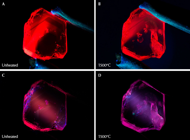
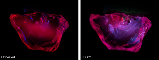
Figure 32. A: Sample 17 displays a strong red fluorescence in long-wave UV illumination prior to heating. B: After heating to 1500°C, the sample continues to display strong red fluorescence in long-wave UV. The area on the right with more visible red fluorescence is due to light striking inclusions that have altered, rather than a change in the stone’s bodycolor. C: The ruby displays a medium red fluorescence in short-wave UV prior to heating. D: The sample develops a medium chalky fluorescence reaction in short-wave illumination after heating to 1500°C. Photos by E. Billie Hughes.
Figure 33. Left: Sample 18 displays a strong red fluorescence in short-wave UV before heat treatment. It retains this appearance after heating to 600°, 750°, 900°, and 1100°C. Right: After heating to 1500°C, it displays a zoned chalky fluorescence in short-wave UV. Photos by E. Billie Hughes.

Short-Wave Fluorescence. We also observed the short-wave UV fluorescence reactions of all 15 specimens before and after each round of heating. Before heating and in subsequent rounds, they displayed a strong pinkish red fluorescence. After the initial rounds of heating to lower temperatures, we observed no significant change in their reactions to short-wave UV. Once the rubies were heated to 1500°C, significant changes were observed. At this point, the samples all developed a strong zoned, chalky pinkish red fluorescence. In some specimens, the reaction was clearly more pinkish red than before heating, as seen in figures 32 and 33. With some samples, the chalkiness was spread across the ruby, while in others the chalky areas were more prominently zoned. Sample 18 (figure 33) showed chalky areas following a clear, angular zone pattern.
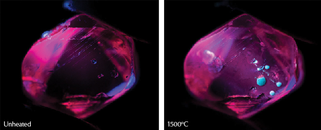
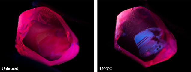
Figure 34. Left: Sample 12 displays strong red fluorescence in short-wave UV before heating and with each subsequent round until the highest temperature round. Right: At a relatively high temperature of 1500°C, it develops a medium chalky fluorescence. The bright round chalky features here are molten material that has hardened on the surface. Photos by E. Billie Hughes.
Figure 35. Left: Sample 46 displays a strong red short-wave fluorescence in its unheated state. Like the other samples tested, it did not display any change in appearance in short-wave UV illumination until after the last round of heating. Right: After heating to 1500°C, the ruby displays a clear, zoned chalky appearance in short-wave UV. Photos by E. Billie Hughes.

Brighter chalky areas concentrated in rounded spots were also seen (see figure 34). Closer observation revealed that these are from molten material that attached and cooled on the surface, rather than from features inside the samples. Treaters will usually repolish or even acid-clean a stone after it has been heated to remove this type of foreign substance, although remnants may be visible upon close microscopic examination. In sample 46 (figure 35), the chalky area seen in short-wave UV after heat treatment is sharply delineated from the rest of the stone.

When corundum is heated and rutile dissolves, this releases Ti4+. Areas with a high concentration of rutile microcrystals and rutile silk can then have a high concentration of Ti4+, which creates zoned areas with chalky fluorescence (Hughes et al., 2017). Sample 18 (figure 33) offers a clear example of the chalkiness associated with a zoned cloud of partially dissolved silk.

A crystal must always be charge-balanced. When a rutile needle begins to dissolve into corundum during heat treatment, Ti4+ is forced into solid solution, and this upsets the charge balance. The dissolution of rutile into corundum is much like a “cylinder” that expands in diameter with time over the course of heating. At the outer edge of this cylinder, the Ti4+ concentration is essentially zero, while the concentration of TiO2 is highest at the center. At some point between these extremes, the concentration of Ti4+ that dissolves into the corundum becomes greater than those of potential acceptors such as Fe2+ and Mg2+, which are the easiest means of achieving charge balance. At that point, Ti4+ begins to be charge-compensated by aluminum vacancies rather than by Mg2+ and Fe2+. One aluminum vacancy has a relative charge of –3 compared to the neutral lattice, so one vacancy charge compensates three Ti4+. It is the various combinations of aluminum vacancies and Ti4+ ions that fluoresce chalky white under short-wave UV light (J. Emmett, pers. comm., 2022).

In this experiment, chalky fluorescence was observed in all samples after heat treatment. This suggests a relatively higher concentration of Ti4+ and lower concentrations of iron and magnesium in the rubies. In corundum containing high concentrations of iron and magnesium, the fluorescence appears weaker or inert (Hughes et al., 2017).

CONCLUSIONS

The presence of low-temperature-heated ruby on the market can present a challenge for gemologists trying to detect treatment. While features such as the appearance of rutile can provide a well-known and helpful indicator for heat treatment at higher temperatures, these tend not to change noticeably at lower temperatures. Observation of short-wave UV fluorescence reactions yielded similar results. When heated to 1500°C, the samples developed a distinctive chalky appearance that could help separate them from unheated material. However, heating to lower temperatures did not produce this telltale sign, nor did the UV-Vis-NIR spectra of the samples yield diagnostic evidence of heat treatment. Therefore, gemologists must rely on other observations to detect low-temperature heat treatment.

Fortunately, in our experiments with heat treatment of Burmese ruby, we observed many types of solid inclusions—including calcite, mica, spinel, and zircon—that are sensitive to heat at lower temperatures between 600° and 1100°C. Careful microscopic observation of these crystals can act as our proverbial canary in the coal mine, providing evidence of heat treatment before other inclusions such as rutile silk show signs of alteration.

Nevertheless, several of these crystals showed no noticeable changes after treatment at lower temperatures. As such, the absence of visual features associated with heat treatment does not mean that stones were not treated at lower temperatures. Micro-Raman analysis of inclusions, particularly spinel inclusions, can support the detection of low-temperature heat treatment, even when visual observations provide no evidence of treatment, reinforcing its utility in the gemological laboratory.

It is inevitable that the boundaries of treatment procedures will continue to be pushed. Detection criteria will require constant updates, based on new research and experiments, to stay in touch with current developments.

E. Billie Hughes is a gemologist and co-founder of Lotus Gemology in Bangkok. Wim Vertriest is manager of field gemology at GIA in Bangkok.

The authors would like to express their gratitude to those who have helped support this project. We thank the Accredited Gemologists Association (United States) for providing a research grant that helped to support and fund this project. We also thank Richard W. Hughes and Wimon Manorotkul (Lotus Gemology, Bangkok), John L. Emmett (Crystal Chemistry, Brush Prairie, Washington), John I. Koivula (GIA, Carlsbad, California), Vincent Pardieu (Bahrain), and Çigdem Lüle (Kybele LLC, Arlington Heights, Illinois) for their advice and assistance. Charuwan Khowpong, Polthep Sukpanish, and Titapa Tanawansombat (GIA, Bangkok) assisted with data collection. Eric Braunwart (Columbia Gem House, Vancouver, Washington) assisted with heating. The authors would also like to thank the peer reviewers for their thoughtful and constructive comments.

Al-Beruni M.A. (1989) The Book Most Comprehensive in Knowledge on Precious Stones: Al-Beruni’s Book on Mineralogy [Kitab al-jamahir fi marifat al-jawahir]. Trans. by H.M. Said, One Hundred Great Books of Islamic Civilization, Natural Sciences No. 66. Pakistan Hijra Council, Islamabad.

Bieri W., Grobety B., Peretti A., Hametner K., Günther D. (2010) Chemical composition of apatite inclusions in corundum and spinel determined by LA-ICP-MS and its potential for authentication and provenance determination. Geochimica et Cosmochimica Acta, Vol. 74, No. 12, p. A89.

Dubinsky E.V., Stone-Sundberg J., Emmett J.L. (2020) A quantitative description of the causes of color in corundum. G&G, Vol. 56, No. 1, pp. 2–28, http://dx.doi.org/10.5741/GEMS.56.1.2

Gillet P., Biellmann C., Reynard B., McMillan P. (1993) Raman spectroscopic studies of carbonates part I: High-pressure and high-temperature behaviour of calcite, magnesite, dolomite and aragonite. Physics and Chemistry of Minerals, Vol. 20, No. 1, pp. 1–18, http://dx.doi.org/10.1007/BF00202245

Harker R.I., Tuttle O.F. (1955) Studies in the system CaO–MgO–CO2; Part 1, The thermal dissociation of calcite, dolomite and magnesite. American Journal of Science, Vol. 253, No. 4, pp. 209–224, http://dx.doi.org/10.2475/ajs.253.4.209

Hughes E.B., Perkins R. (2019) Madagascar sapphire: Low-temperature heat treatment experiments. G&G, Vol. 55, No. 2, pp. 184–197, http://dx.doi.org/10.5741/GEMS.55.2.184

Hughes R.W., Manorotkul W., Hughes E.B. (2017) Ruby & Sapphire: A Gemologist’s Guide. RWH Publishing/Lotus Publishing, Bangkok.

Koivula J.I. (2013) Useful visual clue indicating corundum heat treatment. G&G, Vol. 49, No. 3, pp. 160–161, http://dx.doi.org/10.5741/GEMS.49.3.160

Krishnamurti D. (1957) The Raman spectrum of calcite and its interpretation. Proceedings of the Indian Academy of Sciences - Section A, Vol. 46, No. 3, pp. 183–202, http://dx.doi.org/10.1007/BF03045968

Lafuente B., Downs R.T., Yang H., Stone N. (2015) The power of databases: The RRUFF project. In T. Armbruster and R.M. Danisi, Eds., Highlights in Mineralogical Crystallography, De Gruyter, Berlin, pp. 1–30, https://rruff.info/about/downloads/HMC1-30.pdf

Pardieu V., Saeseaw S., Detroyat S., Raynaud V., Sangsawong S., Bhusrisom T., Engniwat S., Muyal J. (2015) “Low temperature” heat treatment of Mozambique ruby: Results report. GIA News from Research, https://www.gia.edu/doc/Moz_Ruby_LowHT_US.pdf, April 16, 34 pp.

Peretti A., Schmetzer K., Bernhardt H.-J., Mouawad F. (1995) Rubies from Mong Hsu. G&G, Vol. 31, No. 1, pp. 2–26, http://dx.doi.org/10.5741/GEMS.31.1.2

Roedder E. (1984) Fluid Inclusions. Reviews in Mineralogy: Vol. 12. Mineralogical Society of America, Washington, D.C.

Saeseaw S., Wang W., Scarratt K., Emmett J.L., Douthit T.R. (2009) Distinguishing heated spinels from unheated natural spinels and from synthetic spinels: A short review of ongoing research. GIA Research News, https://www.gia.edu/doc/distinguishing-heated-spinels-from-unheated-natural-spinels.pdf, 13 pp.

Saeseaw S., Khowpong C., Vertriest W. (2020) Low-temperature heat treatment of pink sapphires from Ilakaka, Madagascar. G&G, Vol. 56, No. 4, pp. 448–457, http://dx.doi.org/10.5741/GEMS.56.4.448

Sripoonjan T., Wanthanachaisaeng B., Leelawatanasuk T. (2016) Phase transformation of epigenetic iron staining: Indication of low-temperature heat treatment in Mozambique ruby. Journal of Gemmology, Vol. 35, No. 2, pp. 156–161.

Stone-Sundberg J., Thomas T., Sun Z., Guan Y., Cole Z., Equall R., Emmett J.L. (2017) Accurate reporting of key trace elements in ruby and sapphire using matrix-matched standards. G&G, Vol. 53, No. 4, pp. 438–451, http://dx.doi.org/10.5741/GEMS.53.4.438

Stone-Sundberg J.L., Guan Y., Sun Z., Ardon T. (2021) Accurate trace element reporting in corundum: Development of secondary ion mass spectrometry relative sensitivity factors. Geostandards and Geoanalytical Research, Vol. 45, No. 1, pp. 207–221, http://dx.doi.org/10.1111/ggr.12360

Tõnsuaadu K., Gross K.A., Plūduma L., Veiderma M. (2011) A review on the thermal stability of calcium apatites. Journal of Thermal Analysis and Calorimetry, Vol. 110, No. 2, pp. 647–659, http://dx.doi.org/10.1007/s10973-011-1877-y

Wang C.-S., Shen A.H., Liu Y.-G., Zhang Q. (2019) Raman spectra study of heating treatment and order-disorder transition of Cr3+-doped MgAl2O4 spinel. Spectroscopy and Spectral Analysis, Vol. 39, No. 1, pp. 109–113.

Wang W., Scarratt K., Emmett J.L., Breeding C.M., Douthit T.R. (2006) The effects of heat treatment on zircon inclusions in Madagascar sapphires. G&G, Vol. 42, No. 2, pp. 134–150, http://dx.doi.org/10.5741/GEMS.42.2.134

Widmer R., Malsy A.-K., Armbruster T. (2014) Effects of heat treatment on red gemstone spinel: Single-crystal X-ray, Raman, and photoluminescence study. Physics and Chemistry of Minerals, Vol. 42, No. 4, pp. 251–260, http://dx.doi.org/10.1007/s00269-014-0716-7

Yamanaka T., Takéuchi Y. (1983) Order-disorder transition in MgAl2O4 spinel at high temperatures up to 1700°C. Zeitschrift für Kristallographie – Crystalline Materials, Vol. 165, No. 1-4, pp. 65–78, http://dx.doi.org/10.1524/zkri.1983.165.14.65